


Description
Overview:
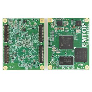
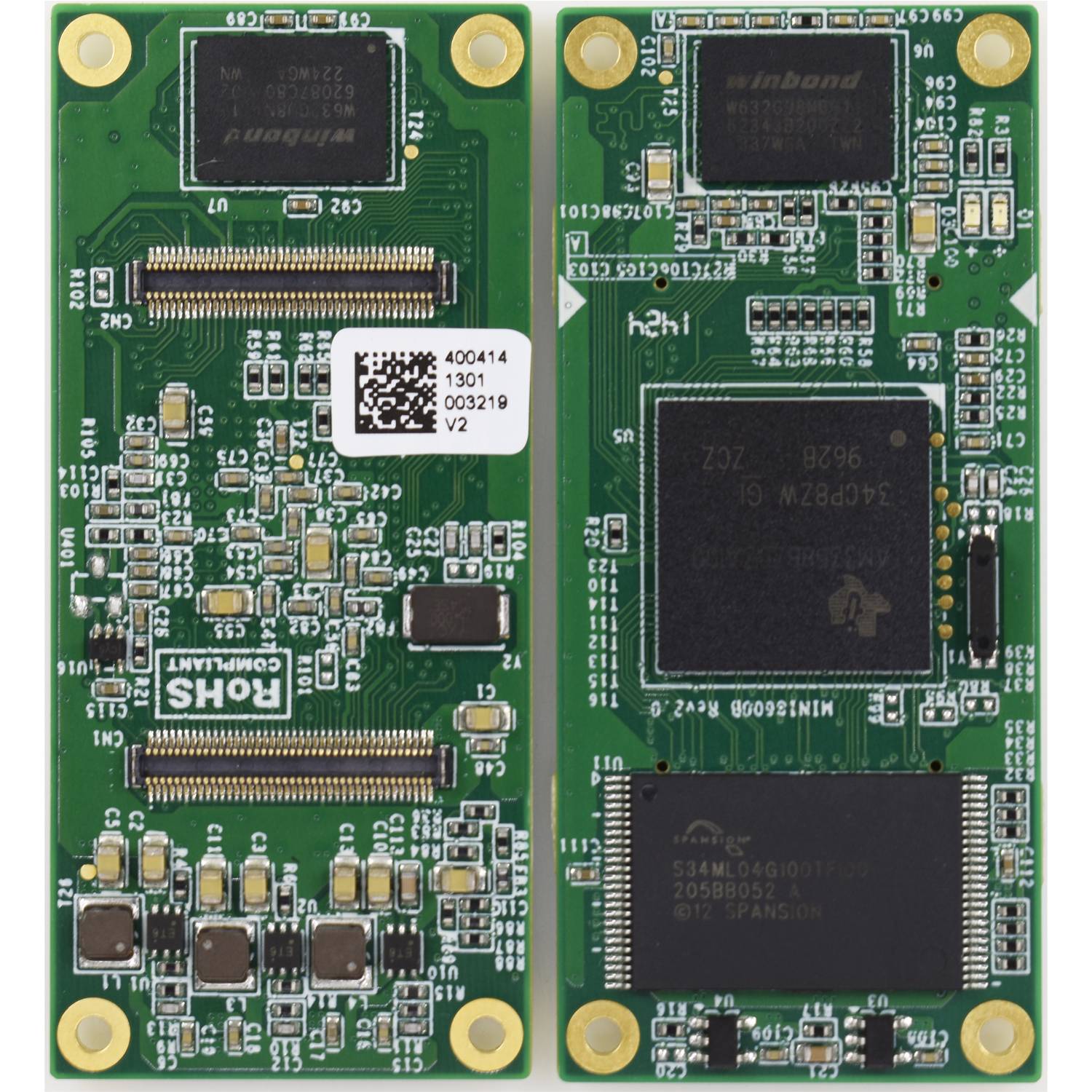
Measuring 60mm by 27mm, a controller board based on TI’s Sitara AM3358 ARM Cortex-A8 high performance processor. The tiny module integrates 2*256MBytes DDR3 SDRAM and 512Mbytes NAND Flash, and uses two 0.4mm space 2*40-pin board-toboard male expansion connectors.
Top-view of SOM-AM335x-MM (Part NO: Mini8600B Rev2.0) CPU Module
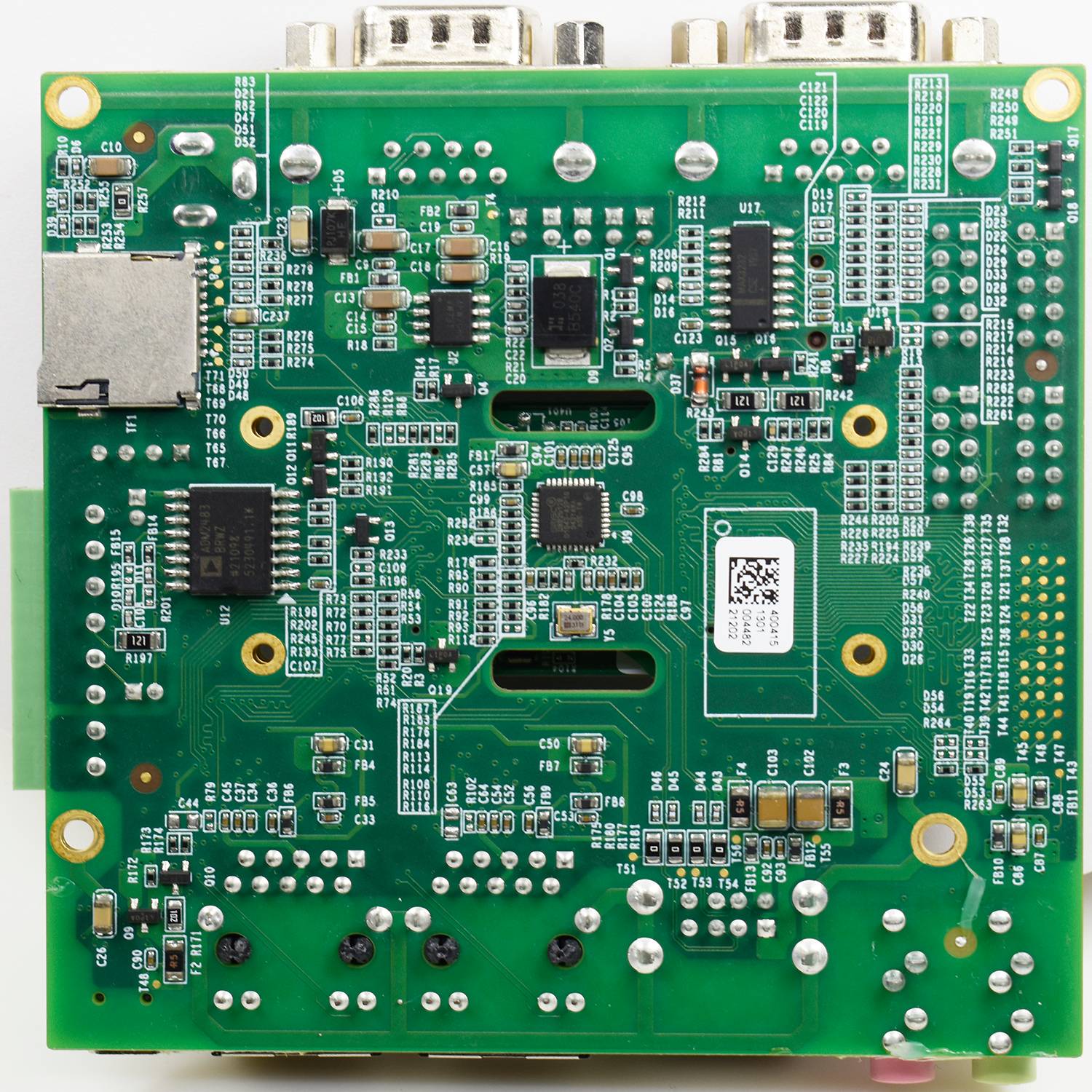
Bottom-view of SOM-AM335x-MM (Part NO:Mini8600B Rev2.0) CPU Module

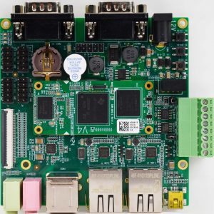
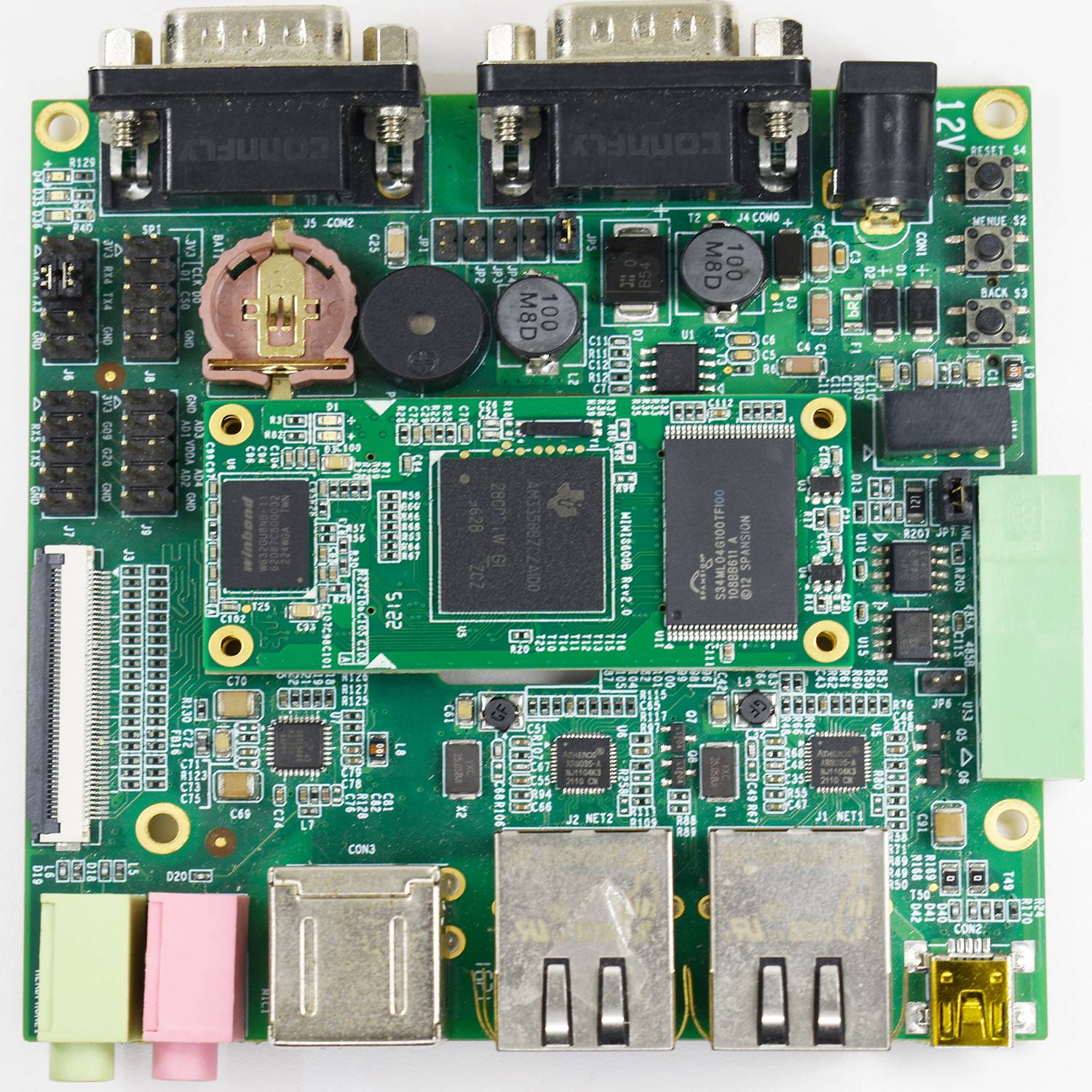
EMTOP has designed a single board computer MINI8600B REV2.0 with standard baseboard SBC8600B REV2.0 which has an expansion board to carry the Mini8600B REV2.0. The flexible design allows the fast and easy way of realizing and upgrading the controller’s capabilities. In additional to those features offered by Mini8600B REV2.0, the Mini8600B REV2.0 with standard baseboard SBC8600B REV2.0 features 5 serial ports (including 2 RS232 and 3 TTL), 2 USB Host and 1 USB OTG, 2 Ethernet ports, CAN, RS485, LCD, Touch screen, Audio, ADC and more other peripherals. The SBC8600B Rev2.0 is a ready-to-run platform to support for Linux 3.2.0, WinCE 7 operating systems.(No support WinCE for industrial version). Mini8600b rev2.0 with standard baseboard SBC8600B REV2.0

System block diagram:

Dimension:

Hardware Features:
Processor/Memory:
- TI AM3358 ARM Cortex-A8 microprocessor
– 1GHz ARM Cortex-A8 32-bit RISC MPU
– NEON SIMD coprocessor for accelerated multimedia/dsp operations
– 32KB/32KB of L1 Instruction/Data Cache with Single-Error Detection (parity)
– 256KB of L2 Cache with Error Correcting Code (ECC)
– SGX530 Graphics Engine
– Programmable Real-Time Unit Subsystem
- 2*256MByte DDR3 SDRAM
- 512MByte NAND Flash
Expansion Interfaces and Signals Routed to Pins:
- Two 0.4mm space 2*40-pin board-to-board male expansion connectors
- TFT LCD Interface (support 24-bpp parallel RGB Interface LCD)
- 2 * USB 2.0 OTG Ports With Integrated PHY, High-Speed
- 3 * inter-integrated circuit (I2C) Bus interfaces
- 6 * UART interfaces;
- 1 * SPI interface;
- Two 10/100/1000 Mb/s Ethernet MAC (EMAC) with Management Data Input/Output
- (MDIO) module;
- A multichannel audio serial ports (McASP);
- 8-channel 12-bit ADC interfaces;
- Two 4-line SD/MMC card interfaces;
- GPMC bus
Electrical Features:
- Dimensions: 60.0 mm x 27.0 mm
- PCB Layers: 8 layers
- Temperature: 0~70 Celsius ( commerial )
-40 ~ 85 Celsius(industrial)
- Humidity Range: 20% ~ 90%
- Input Voltage: 3.3V
EMTOP SOM-AM335x-MM (Part NO: Mini8600B REV2.0) CPU Module is connected to the carrier board via two 0.4mm space 2*40-pin board-to-board male expansion connectors.
The connector marked in red below is CN1; table 1-1 described the pin signals of CN1 connector.

| CN1 | ||
| Pin | Signal | Description |
| 1 | GND | GND |
| 2 | VDDS_RTC | Supply voltage for RTC |
| 3 | CLK_OUT1 | Clock out1 |
| 4 | CLK_OUT2 | Clock out2 |
| 5 | MMC0_DAT0 | MMC0 data bus |
| 6 | MMC0_DAT1 | MMC0 data bus |
| 7 | MMC0_DAT2 | MMC0 data bus |
| 8 | GLOBLE_RESETN | SYS_RESET IN/ OUTPUT |
| 9 | MMC0_DAT3 | MMC0 data bus |
| 10 | AM335X_PWRON_RESETN | CPU PWRON Reset |
| 11 | GND | GND |
| 12 | GND | GND |
| 13 | AM355X_PRU_UART0_CTS | PRU UART0 Clear To Send |
| 14 | AM355X_PRU_UART0_RX | PRU UART0 receive data |
| 15 | AM355X_PRU_UART0_RTS | PRU UART0 request to send |
| 16 | AM355X_PRU_UART0_TX | PRU UART0 transmit data |
| 17 | AM355X_UART0_RX | UART0 receive data |
| 18 | AM355X_UART3_RX | UART3 receive data |
| 19 | AM355X_UART0_TX | UART0 transmit data |
| 20 | AM355X_UART3_TX | UART3 transmit data |
| 21 | AM355X_CAN0_RX | CAN0 receive data |
| 22 | AM355X_I2C0_SDA | I2C0 master serial data |
| 23 | AM355X_CAN0_TX | CAN0 transmit data |
| 24 | AM355X_I2C0_SCL | I2C0 master serial clock |
| 25 | AM355X_UART4_RX | UART4 receive data |
| 26 | AM355X_UART1_RX | UART1 receive data |
| 27 | AM355X_UART4_TX | UART4 transmit data |
| 28 | AM355X_UART1_TX | UART1 transmit data |
| 29 | GND | GND |
| 30 | GND | GND |
| 31 | MII1_COL | MII1 collision detect |
| 32 | AM355X_USB0_DRVVBUS | USB0 controller VBUS control output |
| 33 | MII1_TX_CLK | MII1 transmit clock |
| 34 | AM355X_USB1_DRVVBUS | USB1 controller VBUS control output |
| 35 | MII1_TX_EN | MII1 transmit enable |
| 36 | MII1_REF_CLK | MII1 reference clock |
| 37 | MII1_TXD3 | MII1 transmit data |
| 38 | MII1_CRS | MII1 carrier sense |
| 39 | MII1_TXD2 | MII1 transmit data |
| 40 | MII1_RX_ER | MII1 receive data error |
| 41 | MII1_TXD1 | MII1 transmit data |
| 42 | MII1_RX_DV | MII1 receive data valid |
| 43 | MII1_TXD0 | MII1 transmit data |
| 44 | MII1_RX_CLK | MII1 receive clock |
| 45 | MII_MDIO | MII MDIO DATA |
| 46 | MII1_RXD3 | MII1 receive data |
| 47 | MII_MDC | MII MDIO CLK |
| 48 | MII1_RXD2 | MII1 receive data |
| 49 | GND | GND |
| 50 | MII1_RXD1 | MII1 receive data |
| 51 | AM355X_USB0_DM | USB0 DM- |
| 52 | MII1_RXD0 | MII1 receive data |
| 53 | AM355X_USB0_DP | USB0 DP |
| 54 | MMC0_CMD | MMC0 Command Signal |
| 55 | GND | GND |
| 56 | USB0_VBUS | USB0 bus voltage |
| 57 | AM355X_USB1_DM | USB1 data- |
| 58 | AM355X_USB1_ID | USB1 ID |
| 59 | AM355X_USB1_DP | USB1 data+ |
| 60 | AM355X_USB0_ID | USB0 ID |
| 61 | GND | GND |
| 62 | USB1_VBUS | USB1 bus voltage |
| 63 | GPMC_A0 | GPMC address |
| 64 | GPMC_A7 | GPMC address |
| 65 | GPMC_A5 | GPMC address |
| 66 | GPMC_A11 | GPMC address |
| 67 | GPMC_A4 | GPMC address |
| 68 | GPMC_A10 | GPMC address |
| 69 | GPMC_A3 | GPMC address |
| 70 | GPMC_A9 | GPMC address |
| 71 | GPMC_A2 | GPMC address |
| 72 | GPMC_A8 | GPMC address |
| 73 | GPMC_A6 | GPMC address |
| 74 | GPMC_A1 | GPMC address |
| 75 | GND | GND |
| 76 | GND | GND |
| 77 | VDD_3V3 | Power |
| 78 | VDD_3V3 | Power |
| 79 | VDD_3V3 | Power |
| 80 | VDD_3V3 | Power |
The connector marked in red below is CN2; table 1-2 described the pin signals of CN2 connector.

| CN2 | ||
| Pin | Signal | Description |
| 1 | GND | GND |
| 2 | GND | GND |
| 3 | MCASP0_AHCLKX | MCASP0 transmit master clock |
| 4 | MCASP0_ACLKX | MCASP0 transmit bit clock |
| 5 | MCASP0_FSX | MCASP0 transmit frame sync |
| 6 | MCASP0_AXR0 | MCASP0 serial data(I/O) |
| 7 | MCASP0_AHCLKR | MCASP0 receiver master clock |
| 8 | MMC0_CLK | MMC0 clock |
| 9 | MCASP0_FSR | MCASP0 receive frame sync |
| 10 | MCASP0_AXR1 | MCASP0 serial data(I/O) |
| 11 | GND | GND |
| 12 | GND | GND |
| 13 | VDDA_ADC | Supply voltage range for ADC |
| 14 | AM355X_ADC0 | ADC0 |
| 15 | AM355X_ADC1 | ADC1 |
| 16 | AM355X_ADC2 | ADC2 |
| 17 | AM355X_ADC3 | ADC3 |
| 18 | AM355X_ADC4 | ADC4 |
| 19 | AM355X_ADC5 | ADC5 |
| 20 | AM355X_ADC6 | ADC6 |
| 21 | AM355X_ADC7 | ADC7 |
| 22 | GND_ADC | GND ADC |
| 23 | GND | GND |
| 24 | GND | GND |
| 25 | LCD_DATA1 | LCD data bus |
| 26 | LCD_DATA12 | LCD data bus |
| 27 | LCD_DATA0 | LCD data bus |
| 28 | LCD_DATA10 | LCD data bus |
| 29 | LCD_DATA5 | LCD data bus |
| 30 | LCD_DATA13 | LCD data bus |
| 31 | LCD_DATA4 | LCD data bus |
| 32 | LCD_DATA11 | LCD data bus |
| 33 | LCD_DATA6 | LCD data bus |
| 34 | LCD_DATA14 | LCD data bus |
| 35 | LCD_DATA8 | LCD data bus |
| 36 | LCD_VSYNC | LCD vertical sync |
| 37 | GND | GND |
| 38 | GND | GND |
| 39 | LCD_DATA9 | LCD data bus |
| 40 | LCD_PCLK | LCD pixel clock |
| 41 | LCD_DATA15 | LCD data bus |
| 42 | GPMC_AD11 | GPMC address & data |
| 43 | LCD_DATA3 | LCD data bus |
| 44 | GPMC_AD15 | GPMC address & data |
| 45 | LCD_DATA2 | LCD data bus |
| 46 | GPMC_AD14 | GPMC address & data |
| 47 | LCD_DATA7 | LCD data bus |
| 48 | GPMC_WAIT0 | GPMC wait0 |
| 49 | LCD_HSYNC | LCD horizontal sync |
| 50 | GPMC_BEN1 | GPMC byte enable 1 |
| 51 | GND | GND |
| 52 | GND | GND |
| 53 | LCD_EN | LCD AC bias enable chip select |
| 54 | GPMC_WPN | GPMC write protect |
| 55 | GPMC_AD13 | GPMC address & data |
| 56 | GPMC_CSN3 | GPMC chip select |
| 57 | GPMC_AD9 | GPMC address & data |
| 58 | GPMC_CSN2 | GPMC chip select |
| 59 | GPMC_AD10 | GPMC address & data |
| 60 | GPMC_CLK | GPMC clock |
| 61 | GPMC_AD8 | GPMC address & data |
| 62 | GPMC_AD6 | GPMC address & data |
| 63 | GPMC_AD12 | GPMC address & data |
| 64 | GND | GND |
| 65 | GND | GND |
| 66 | GPMC_CSN1 | GPMC chip select1 |
| 67 | GPMC_ADVN_ALE | GPMC address valid/address latch enable |
| 68 | GPMC_AD5 | GPMC address & data |
| 69 | GPMC_BEN0_CLE | GPMC byte enable 0/Command latch enable |
| 70 | GPMC_AD4 | GPMC address & data |
| 71 | GPMC_OEN_REN | GPMC output /read enable |
| 72 | GPMC_AD1 | GPMC address & data |
| 73 | GPMC_AD2 | GPMC address & data |
| 74 | GPMC_AD0 | GPMC address & data |
| 75 | GPMC_AD3 | GPMC address & data |
| 76 | GPMC_CSN0 | GPMC chip select0 |
| 77 | GPMC_AD7 | GPMC address & data |
| 78 | GPMC_WEN | GPMC write enable |
| 79 | GND | GND |
| 80 | GND | GND |
Software Features:
| OS | Item | Remark | ||
| Linux | BIOS | SPL (First boot loader) |
NAND | |
| MMC/SD | ||||
| FAT | ||||
| U-boot (Second boot loader) |
NAND | |||
| MMC/SD | ||||
| FAT | ||||
| NET | ||||
| Kernel | Linux-3.2.0 | Supports ROM/CRAM/EXT2/EXT3/FAT/NFS/ JFFS2/UBIFS file systems | ||
| Driver | NAND Flash, SDRAM, Serial port, RTC, Ethernet, TFT LCD, Touch screen, TF card, USB OTG, Audio input/output, LED, Key, CAN, RS485, Power Management (backlight, PWM, ADC) (provided with source code) |
|||
| 2D/3D (not provided with source code) | ||||
| Android | Kernel | Linux-3.2.0 | Gingerbread | |
| Driver | NAND Flash, SDRAM, Serial port, RTC, Ethernet, TFT LCD, Touch screen, TF card, USB OTG, Audio input/output, LED, Key, Power Management (backlight, PWM) (provided with source code) |
|||
| 2D/3D (not provided with source code) | ||||
| WinCE7 | BIOS | X-loader (First boot loader) |
NAND | |
| MMC/SD | ||||
| FAT | ||||
| EBOOT (Second boot loader) |
NAND | |||
| MMC/SD | ||||
| FAT | ||||
| NET | ||||
| OAL | OAL module | Boot parameter | ||
| KILT(EMAC) | ||||
| Serial debug | ||||
| REBOOT | ||||
| Watchdog | ||||
| RTC | ||||
| Kernel profiler | ||||
| System timer | ||||
| Interrupt controller | ||||
| MMU | ||||
| Driver | NAND Flash, SDRAM, Serial port, RTC, Ethernet, TFT LCD, Touch screen, TF card, USB OTG, Audio input/output, LED, Key, RS485, Power Management (backlight) (provided with source code) |
|||
| CAN, 2D/3D (not provided with source code) | ||||
Applications:
- Intelligent Display Terminal
- Medical Equipment
- Smart Appliances
- Alternative Energy Device
- Intelligent Display Terminal
- Blood analyzer
- Robotic Arm
- Charging Station